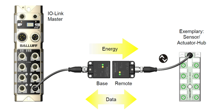
Balluff's wireless coupler installation requirements
Balluff wireless coupler installation has certain requirements:
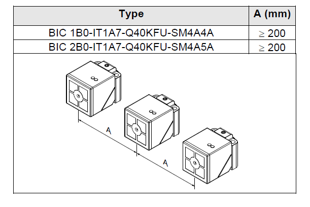
Mutual interference, in order to prevent mutual interference with adjacent bases or remote devices, the minimum distance must be observed.
- BIC 1B0-IT1A7-Q40KFU- SM4A4A A> = 200;
- BIC 2B0-IT1A7-Q40KFU-SM4A5A A> = 200;
Installation on metal Requirements: damage to the device due to induction effects!
Metal objects in front of and above the coil cap heat the induction surface.
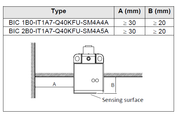
The sensing surface is marked by a cross-hair on the housing. Install the assembly so that metal objects are not in the area where distances A and B are generated.
Distances A and B must be kept independent of each other.
- BIC 1B0-IT1A7-Q40KFU-SM4A4A A> = 30, B> = 20;
- BIC 2B0-IT1A7-Q40KFU-SM4A5A A> = 30, B> = 20;
- distance / offset BIC 1B0-IT1A7-Q40KFU-SM4A4A A <= 5, B <= 5;
- BIC 2B0-IT1A7-Q40KFU-SM4A5A A <= 5, B <= 5, the system can be operated at a larger distance and / or offset.
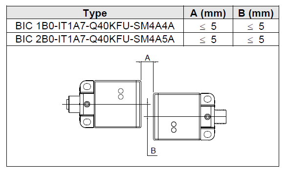
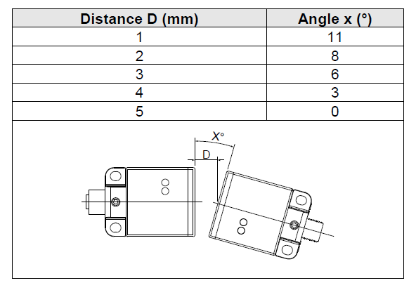
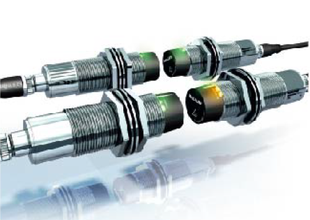
Find out the power transmitted by the system. The connector inserts on the base and remote control can be rotated 180 °.
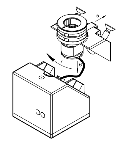
To do this, follow the disassembly steps described below. After the connector is inserted and rotated, the subsequent reassembly is performed in the reverse order.
The maximum transmission power of the BIC system depends on the distance and the axial and angular offset. In the case where the distance is 5 mm, the lateral offset is 5 mm, and there is no angular offset, the output current shown in 1A electrical data is guaranteed.
Please see operation manual for details.
